Basic circuit diagram for the unit..
WARNING: 230-240VAC can kill. Do not attempt this project unless you have a good understanding of power and electronics. A simple mistake can result in serious injury or death. If you have any doubts at all, please consult a licensed electrician.
Long term loss of power to the aquarium is not good for our aquarium inhabitants and can result in a serious lack of oxygen. Normal circulation brings oxygenated water from the surface to other areas within the tank and also takes water with higher levels of carbon dioxide to the surface where it escapes. Without power, all circulation stops which only leaves diffusion which is very inefficient. Additionally, without power, there is little light which means photosynthetic organisms are no longer producing more oxygen than they consume and this create even more demand for the already low concentration of oxygen. Low oxygen can cause death in many organisms, especially fish. Adding a small amount of circulation under these conditions can greatly increase the available oxygen and mean the difference between losses and riding out the lack of power.
There are a number of ways circulation can be provided, but any method that is automatic is going to be significantly better as it will work even if you are not at home. If the method makes use of existing pumps, it is even better as it can be both nonintrusive and convenient. The simplest off-the-shelf method is a purpose built Uninterruptible Power Supply (UPS) most usually available for computers. There are a number of brands available such as American Power Conversion (APC). Unfortunately, these can be expensive and have a limited life (probably only around 3 years).
A car battery and an inverter can provide an inexpensive alternative to a UPS, however, on their own they do not provide an automatic method of switching from mains to battery. This project provides a relatively simple device which allows you to drive a number of circulation pumps off mains power while it is available and then automatically switch to battery power when the mains drops out. Please note that this project deals with lethal voltages and all care must be taken.
The heart of the unit is the Double Pole Double Throw (DPDT) relay. With power to the relay (from the mains), Active and Neutral from the mains input is connected to the output powerpoint. When the mains power drops out, the relay switches off so that it connects Active and Neutral from the Inverter to the outlet. A Double Pole relay allows both Active and Neutral to be switched. Double Throw means that a connection can be made in both positions (when the relay is on and off). See the circuit diagram below.
Power to the relay is provided by a transformer running of the mains input. The transformer drops the voltage from 240VAC to around 12VAC. As the relay runs off 12VDC, a rectifier bridge must be used to convert the alternating current to direct current.
Basic circuit diagram for the unit..
I have chosen to use a 1A fuse on the switch box output. While the inverter has overload protection, without the fuse, a load of greater than 300W would be possible while running off mains power and I didn't want the possibility of accidentally adding too much load (unlikely, I know) and then having the unit fail in the event of loss of power. A 1A fuse will restrict the load to 240W.
Note that different voltages can be used for the transformer and relay as long as they both match. For example, a 9V transformer can be used instead as long as the relay also works off 9 volts.
| Component | Cost | Place of purchase |
| Metal Box | $25.75 |
Jaycar |
| 12VDC DPDT 10A Relay | $11.25 |
Jaycar |
| Base for relay | $10.00 |
Jaycar |
| 12V 200mA Transformer | $3.50 |
Jaycar |
| 1.2A 400V Rectifier Bridge | $0.50 |
Jaycar |
| 3AG Panel Mount Fuse holder | $1.65 |
Jaycar |
| 1A Fuse | $1.30 |
Dick Smith Powerhouse |
| Double Powerpoint | $9.85 |
Hardwarehouse |
| 2 3 Pin Plugs | $4.44 |
Hardwarehouse |
| Bolts and Nuts | ||
| 3 core flex and hookup wire | ||
| Connector strip | ||
| Spaghetti tubes | ||
| Total | $68.24 |
Other components:
| Component | Cost | Place of purchase |
| 300W Isolated Inverter | $129.50 |
Jaycar |
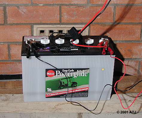
| 85AH Deep Cycle Battery | $149.00 |
Battery World |
| Projecta 2200mA Charge 'n Maintain Charger | $69.99 |
Kmart |
| Plug-in Safety Switch | $19.45 |
Hardwarehouse |
| Total | $367.92 |
Tools required
Construction is fairly straight forward. The box needs to be drilled and cut to take the components. I cut a hole in the "front" face to take the double powerpoint as well as a hole for the fuse holder. I drilled two holes in the "back" panel for the mains and inverter input cables. I drilled holes in the base to mount the transformer, connector strip and relay base.
Wiring connections are as follows:
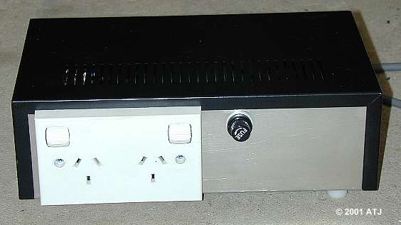
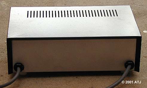
Rear panel of the switch box. The left hand cable is mains input and the right is inverter input.
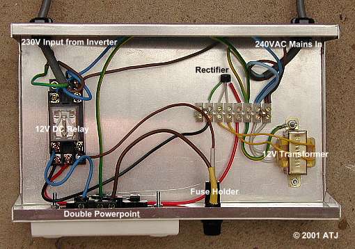
Inside the switch box.
As this unit makes use of a unsealed lead acid battery, it is not the sort of thing you want in the lounge room. My unit is to provide backup power to the 6 tanks I have under the house. I have placed the battery some distance away from the tanks next to a vent in the wall. This should provide adequate ventilation and prevent the build up of flammable gases from battery charging. The battery charger, inverter and switch box sit on a shelf above the battery.
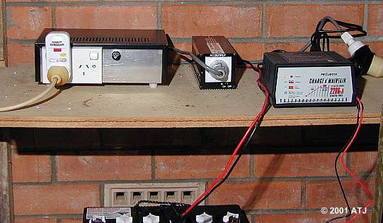
Switch Box, Inverter and Charger.
Both the battery charger and the inverter are connected to the battery terminals using the provided clips.
The battery charger mains inlet and the switch box mains inlet are connected to the mains.
The switch box inverter inlet is connected to the output of the inverter.
A plug-in safety switch is first plugged into one of the sockets on the double powerpoint. A safety switch is required as the inverter is isolated from the mains power. If earth leakage occurred with a device connected through the switch box without a secondary safety switch, it would trip the main safety switch. This in turn would bring the inverter into operation without protection. With a secondary safety switch in operation, it is likely to trip on its own, leaving other mains powered devices working.
An extension cord is connected to the safety switch and run to a switchable powerboard behind the 2 Reef tanks. The powerboard is mounted on the wall.
The sump return pumps on both Reef tanks as well as the calcium carbonate reactor circulation pump are connected to the powerboard.
As discussed above, you need to provide sufficient circulation during loss of power to ensure adequate levels of oxygen in the tank. In most tanks the sump return pump should be sufficient but it may be necessary to run some powerheads in heavily populated tanks. While more pumps will increase available oxygen, they will also draw more power, decreasing the time the battery will provide power. You must choose between these two constraints.
The battery I am using is rated at 85AH which means, in theory, it will run a load of 1 amp for 85 hours, a 10 amp load for 8.5 hours or an 85 amp load for 1 hour. The salesman at Battery World told me that in Australia, the batteries are rated on their initial run time and after a few cycles the battery should last longer, however, for calculations I will assume 85AH.
The inverter is rated at 300W with 90% efficiency, however, I plan on only using a load of around 50W. I bought an inverter that was rated higher than I need for normal use as there may be occasion when more power is required.
A 50W load with 100% efficiency would draw 4.17 amps (50W/12V). However, with 90% efficiency, the current drawn will be around 4.6 amps. This means the battery should be able to provide 50W for just over 18 hours. If I was to cut the power used to 25W, I would effectively double the running time. Addition of a solar panel that provides 80W of power would mean the system would run indefinitely under sunny conditions.
Last updated: 26 September 2007