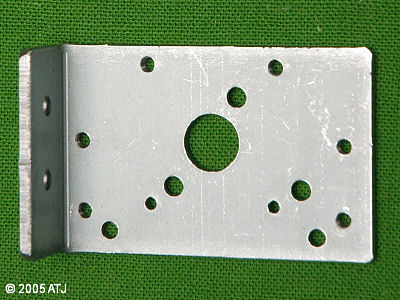
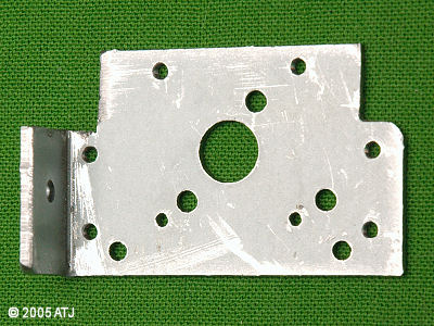
Figure 1: Top: the mounting bracket as supplied; Bottom: the mounting bracket with the corners removed.
WARNING: 230-240VAC can kill. Do not attempt this project unless you have a good understanding of power and electronics. A simple mistake can result in serious injury or death. If you have any doubts at all, please consult a licensed electrician.
In a recent group order on Reefing The Australian Way (Group order of Peristaltic Pumps), I purchased some peristaltic pumps from Williamson Pumps in the UK. The models purchased were Series 100 with 240VAC 15rpm motors and Norprene tubing. These have a flow rate of around 150 mL/hr and so a maximum of 3.6L could be delivered in a day.
The motor and pumps come bare and so for neatness and safety a housing is required. Additionally, 2 or 3 core flex and a plug is required to provide power to the pump.
| Component | Cost | Place of purchase | Part number |
| Peristaltic Pump and motor | $70.63 | Williamson Pumps | Series 100 |
| Polycarbonate Box (82 x 80 x 55mm) | $9.99 | Dick Smith Powehouse | H2869 |
| Terminal Strip (12 way) only 2 used | $1.55 | Jaycar Electronics | HM3194 |
| Plug (3 pin 240VAC 10A ) | $1.98 | Bunnings | |
| Cable (3 Core 7.5A) - 1m | $1.71 | Bunnings | |
| Total | $85.86 |
The lid of the polycarbonate box has ridges (for sealing) which get in the way of the mounting bracket on the motor. The corners needed to be trimmed off the mounting bracket so that the bracket will fitted into the lid.
I used a hack saw to cut the corners and then smoothed the cut edges with a file.
Figure 1: Top: the mounting bracket as supplied; Bottom: the mounting bracket with the corners removed.
Holes needed to be drilled in the lid of the box to allow for the drive shaft of the motor and the mounting screws and location lugs of the pump. I held the bracket inside the lid and used it as a template for the holes. I drilled smaller holes first (the maximum size I could given the holes in the bracket) and then redrilled the holes with the appropriate sized bits required for the bolts, shaft and lugs.
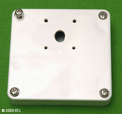
Figure 2: The lid showing the holes.
I attached the mounting bracket to the motor. I then fitted the motor and bracket through the inside of the lid of the box. I mounted the pump onto the shaft of the motor and screwed in the two holding bolts.
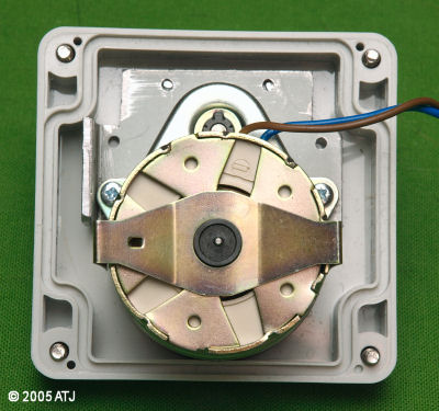
Figure 3: The lid with the motor mounted.
I drilled a hole in the side of the box for the 3 core flex. I made sure there was clearance around the motor when it is inside the box. The hole was the same size as the diameter of the flex so it is a tight fit. I striped a length of the outer insulator and striped the ends of the brown (active) and blue (neutral) cables. I connected the brown cable from the flex to the brown cable of the motor and the blue cable of the flex to the blue cable of the motor using the terminal strip.
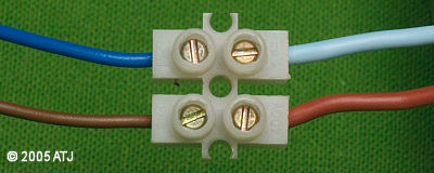
Figure 4: The connected wires.
The box is to be mounted on a wall, so I drilled an upside-down keyhole in the back of the box to allow it to be hung on a screw. I drilled one hole the size of the head of the screw and another above it the size of the shaft of the screw and joined the two holes by filing the material in-between.
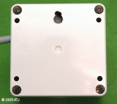 Figure 5: The back of the box with hanging hole.
I fitted the lid with the motor-pump assmebly attached into the box and fastened with the 4 screws.
I used a length of 3mm airline from the reservoir under the tank to the input of the pump. I used a ceramic airstone at the other end of the airline to act as both a weight and a filter. I used another length of 3mm airline to run from the outlet of the pump to the tank. The outlet of the airline is positioned so that it is out of the water and drips directly onto the outlet of the skimmer to make sure the water is well aerated (saturated with carbon dioxide). The reservoir contains Kalkwasser decanted from my Bulk Kalkwasser.
The peristaltic pump is connected to one of my Auto Top-off II devices to automatically top-off the tank.
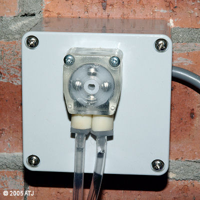
Figure 6: The completed pump housing.
Last updated: 24 November 2005